| ||||||
ASL Overview | ||||||


- Date:
- December 6, 2004
- April 3, 2007
Abstract
- This document serves as an overview to the Adobe Source Libraries (ASL). The goal of ASL is to develop the technology necessary to construct commercial applications by assembling generic algorithms through declarative descriptions.
- The first two significant libraries in ASL are known as the property model library (Adam) and layout library (Eve). They are components for modeling the human interface appearance and behavior in a software application. The property model library and layout library are described along with related libraries.
- ASL is a project within the Adobe Software Technology Lab (STLab); a research group chartered with increasing developer productivity and software quality through better technologies and education.
- Adobe Begin is a sample application aimed at implementing the ideas expressed herein. A Widget Reference is available to assist users in the creation of dialogs. There are also many prebuilt dialogs provided from which you can learn by example.
Table of Contents
Introduction to the Property Model and Layout Libaries
- The property model library consists of a solver and a declarative language for describing constraints and relationships on a collection of values, typically the parameters to an application command (a function). When bound to a human interface (HI), the property model library provides the logic that controls the HI behavior. A property model is similar in concept to a spreadsheet or a forms manager. Values are set and dependent values are recalculated. The property model library provides facilites to resolve interrelated values, but is not a general constraint system.
- The layout library consists of a solver and a declarative language for constructing an HI. The layout solver takes into account a rich description of HI elements to achieve a high quality layout rivaling what can be achieved with manual placement. A single HI description suffices for multiple OS platforms and languages. The layout library was developed to work with the property model library but can also be used alone.
- These libraries do not constitute a traditional application framework. They are component libraries which can be incorporated into a number of environments. They can be used together, or independently, but must be combined with other facilities to construct an application. Nearly all of the components which comprise the property model and layout libraries can also be used independently and are documented as part of ASL.
- ASL is being developed in C++, and relies heavily on the Boost libraries <http://www.boost.org/> which are required for building ASL.
- The layout library was developed with three primary goals and two requirements.
- Goals:
- Make it easier to specify and modify the layout of a human interface.
- Have a single definition of the interface for all platforms.
- Have a single definition of the interface for all languages.
- Requirements:
- Must allow piecemeal incorporation into an application.
- Generate layouts as good or better than those generated by hand.
- Goal 3 relies on a tokenized string system. ASL provides the xstring library as an example of such a system, but the layout library is not directly dependent on any string system.
- The following example is used throughout this document. It is introduced here to give a feel for what these libraries are and what they do. A simple layout description of a dialog looks like this:
layout clipping_path
{
    view dialog(name: "Clipping Path")
    {
        column(child_horizontal: align_fill)
        {
            popup(name: "Path:", bind: @path, items:
            [
                { name: "None", value: empty },
                { name: "Path 1", value: 1 },
                { name: "Path 2", value: 2 }
            ]);
            edit_number(name: "Flatness:", digits: 9, bind: @flatness);
        }
        button(name: "OK", default: true, bind: @result);
    }
}
- Note: For brevity, strings are shown in a simplified form. Normally, a tokenized string system would be used.
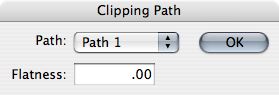
Figure 1: The Clipping Path dialog described above in Mac OS X
- Although this example creates a static layout, the layout library can also control the placement of HI elements when elements are hidden or revealed, as a window resizes, or as content changes.
- The
bindattributes in the layout description are what connect the HI elements to an underlying model. In this case the model is a model of the parameters to a function (presumably a function to change the "clipping path" of a document). The property model library manages the constraints and relationships amongst the parameters taking input from HI events, and feeding information back to the widgets for display.
- The value of the
bindattribute refer to a cell in the property model. The property model for this example is declared as:sheet clipping_path { output: result <== { path: path, flatness: flatness }; interface: unlink flatness : 0.0 <== (path == empty) ? 0.0 : flatness; path : 1; }
- Binding the numeric text field to the flatness cell in the property model binds the HI display to the value in this cell and also binds the enabled state of the HI to the contributing state of the cell in the model. The text field will toggle between "0.0" and the last user-entered value as the popup is switched between "None" and one of the available paths in the document. When "None" is selected the text field will also be dimmed (in a disabled state) because the flatness cell cannot directly contribute to
result; entering a number in the field (and hence setting the flatness cell value) would have no effect onresultso the control is disabled.
- Although changes in the model are reflected in the bound HI, the model does not refer to the HI and is entirely independent. It could be bound to any number of alternate interfaces and the same model is used for script validation. The model is also used for script generation (recording).
- Although these libraries are being developed to solve problems with application HI development for Adobe products, there are other possible uses of the technology. They could be applied to form layout and logic, web application front-end development, web page layout and logic, or document style sheet layout.
- We are also working to extend the concepts in these libraries to apply to the document model within an application.
Goals for Property Model Library
- The goals of the property model library are lofty - in part because for this library to be successful it has to be a significantly better way to build the HI component of an application.
Decreasing the Effort Required to Construct an Interface
- Ask nearly any software engineer what they hate doing most and the answer will be "building the human interface." Even working on products where the layout library has been adopted, and the engineers are freed from much of the mundane tasks such as getting a button at just the right pixel location; the effort to build the human interface is onerous. In fact, the code associated with the human interface accounts for nearly 1/3 of the code necessary to implement a feature within Adobe applications. Contrast that to the framework code, which accounts for roughly 1/10th of the code in our applications and the potential impact of this project becomes apparent.
- The property model library seeks to provide a clear format for modeling what is now managed with complicated event handling code. It also reduces the amount of redundant logic and consolidates common logic for reuse and sharing. The property model library is targeted to replace the current code necessary to implement an interface with description that is a 10:1 reduction in size and complexity and has been shown to achieve as much as a 600:1 reduction.
Increase the Quality of the Interface Implementation
- As noted above, there is significant code in Adobe products to manage the HI, and one would expect a proportionate number of bugs. But in reality the number of HI-related bugs is disproportionately high (An explanation for this is detailed below). In sampling one of every 500 bugs in Photoshop's 20,000-bug database, roughly half (in this case it was exactly half) of the bugs fell into the interface layer that the property model targets. These bugs tend to be of lower severity than other bugs but still represent a significant impact on resources. Reviewing bugs across a range of Adobe products revealed that roughly 40% of Adobe products' bugs are "behavioral" in nature. Many of these bugs (4 out of 20 in the Photoshop sampling) simply could not have happened using the property model library. Other bugs, though they may still occur, will be easier to find and fix or will be eliminated altogether by moving more of the implementation closer to the design process.
Allow Interfaces to be Shared Across Products
- Adobe's applications have been acquired from other companies and developed internally over more than a decade. Over time, platform requirements have changed and the products have been ported and adapted. The result is that no two major applications are built upon the same application framework.
- Increasingly, our applications are expected to share significant HI elements as they are merged into suites and move beyond the role of an isolated domain to a component in a larger workflow. Areas such as file and asset management, text, color, metadata, web optimization, and transparency, are all expected to be both well integrated into each application and common amongst all of them. The layout library has enabled some level of interface layout sharing already.
- Integration and code sharing is made difficult because of the disparity between frameworks and object models between applications. Even when the layout is shared, the underlying implementation cannot be shared while still meeting the requirement of being well integrated. The result is that the code comprising the logic behind an HI is replicated for each application using the client application model for widgets and event handling. This is a significant amount of duplicated code and effort. The property model library seeks to consolidate that logic and allow it to be moved and customized easily between our applications regardless of the underlying framework.
Shifting HI Development to the Designer
- Currently, a human interface designer is responsible for designing the visuals and may provide some textual description of the behavior. This work is done using graphical tools, such as Photoshop, to draw the interface and annotations are added to describe the behavior. The design is then given to an engineer who "codes" both the layout and the behavior. Sometimes the requested behaviors violate the requirements of the underlying command, forcing the engineer to go back to the designer and resolve the conflicts. It is only after the design is fully implemented by the engineer that significant user testing can take place, usually requiring rework and one or more iterations through the process.
- A visual tool built around the layout library would allow the designer to layout the interface in a form that could be used directly by the application developer. Incorporating property model support into such a tool would serve to increase the communication between the development engineer and interface designer by surfacing the constraints and allowing the designer to experiment with correctly functioning interfaces.
Understanding The Property Model Library
- The design of Adobe's professional applications follow a typical model, view, controller pattern. The model represents the document being edited, and the view is the display of the document within a window. The "controller" is a collection of commands that can be used to modify the document. These commands follow a command pattern (see Gamma, et. al. p. 233) and execute against the document as an undoable transaction.
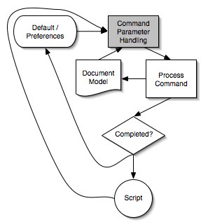
Figure 2: The typical flow of command parameters within an application
- Most of our applications follow this diagram or some variation on the pattern. In this pattern, information from defaults or preferences, or possibly from a script, are combined with state information about the target document. This information, possibly with information provided by the user, is then used to construct the parameters to a command. The command is then executed against the document. If this transaction completes successfully (it may fail if resources are insufficient or the user cancels the operation) then the settings for the command are sent to the scripting system for recording and saved in the preferences. The shaded box is where the command parameters are input by the user and/or validated before handing them off for processing. This is the area where the property model library is focused, with facilities to bind into the rest of the application architecture.
- The parameters for a command may be dependent on, or defaulted based on, the state of the document model.
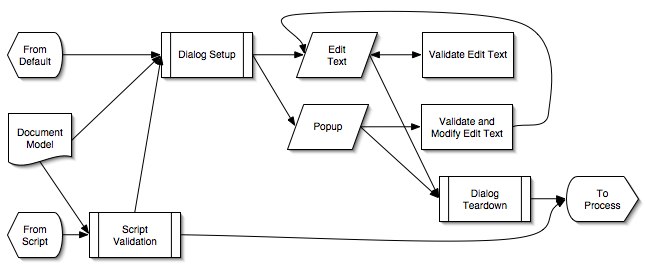
Figure 3: The Edit Text Field Depending Upon the State of the Popup
- The figure above illustrates what happens as part of the command parameter handling process. This is a depiction of the clipping path example used above. Information is fed into the system from a set of defaults (usually what the user selected last) or a script and combined with information from the current document state. This information is fed to the dialog setup code that populates fields and controls within the dialog. (The controls have been formatted either from an appropriate resource description or using the layout library). [****STOPPED HERE****] As the controls in the interface are manipulated, events are generated and other controls are updated in response to reflect validated parameters. Finally, usually in response to the user selecting "OK", the information from the HI fields is gathered, a final validation occurs, the dialog is taken down, and the parameters are sent off for processing. In cases were there is no "cross-talk" between items in the dialog, the behaviors can be coded as simple validating filters attached to each item (for example, a filter on a text edit field that only accepts numbers). More complicated filters can handle simple ranges of values - or combine a couple of HI elements into a standard cluster (like an edit text field bound to a slider). However, even with these simplifications there is duplication of validation code between the scripting validation and that scattered amongst the HI elements. There is custom code required to set-up, teardown, and manage the interaction of the dialog (in very trivial cases the interaction may be managed completely by stock filters).
- The command interface is not limited to modal dialogs. Palette interfaces and direct manipulations also construct command parameters. The property model library can be applied in these cases as well.
- Although this "simple" example does not show it, the interrelationships will quickly exceed the number of items, bounded by (N2 - N) directional relationships for a fully connected set. A dialog can get prohibitively complicated. For example, the Layer Effects dialog in Photoshop 6 has over 250 elements. Although the interaction between elements is somewhat limited, the resulting complexity is still significant. A dialog such as Image Size only has a handful of items, but is fully interconnected. The resulting pages of logic, despite having been worked on across several releases of Photoshop, are an ongoing source of bugs and bug fixes. Even when implemented with the utmost care, these fixes frequently generate other defects.
- All of the code in these event-based systems is tightly bound both to the application framework and to the application document model. This tight coupling prohibits the code from being reused within another application.
Modelling the Controller
- In more complicated cases (such as a slider connected to an edit text field) the result is a tangle of circular dependencies. A deeper analysis reveals that the cycles are created because the HI controls are providing two functions - they are both a display and an input. By logically separating these two functions the circular dependencies are broken. Much of the logic that was in the event handlers, script validation, setup, and teardown can now be collapsed into a single "model". What we are left with is a traditional model / view / controller pattern with the HI controls acting as both view and controller. This is depicted in Figure 4. What is being modeled is the parameters to the command that is being constructed. This model is independent of the HI that is bound to it, allowing the designer greater flexibility in changing the layout and the choice of HI elements without impacting the underlying model.
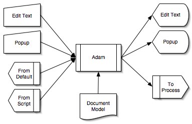
Figure 4: HI Widgets Acting as Both View and Controller Being Split by Adam
- This consolidation alone reduces the complexity of the system from (N2 - N) to simply N. Further, the logic that was replicated between the script validation and the dialog validation can now be shared. Because there is a single model containing the state of the system some of the relationships that had to be coded individually before can now be encapsulated into simple "rules" applied to the system as a whole. For example, any HI designer will tell you that an interface element should be visually disabled if, given the current state of the other interface items, it would have no effect. In a typical event handling system there is no way to determine what will or will not have an effect. With Adam, this rule can be expressed once for the application rather than once for each element that contributes to the enabled state of another.
- The Adam modeling system is conceptually similar to a traditional spreadsheet. Cells are named with text identifiers rather than being organized into a row / column layout and grouped into a "sheet". A "sheet" is similar to a C structure, except data members are cells that can have expressions attached which are evaluated when dependent members are modified. The dependency engine is bidirectional, allowing for queries on a given state such as "what input cells effect the output cells." These types of queries are used to drive the enabled state within the controller (if an input cannot affect any output then the controller attached to the input cell is disabled). The reverse dependency lookup is also used for invariant testing, enabling the engine to report what input cells contributed to an invariant violation, not just that one occurred..
Adam & Eve Architecture
Overview
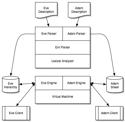
Figure 5: The Basic Components of Adam And Eve and How They Interrelate
- There are two major components: the parsers and the engines. Eve1 has its own language loosely based on a C syntax. The parser in Eve1 is coupled to the Eve1 engine, making it difficult to provide alternate syntaxes. For Eve2 and Adam the engines are completely decoupled from the language allowing for alternate syntaxes to be developed by providing a parser. Optionally, a formatter can also be provided for direct generation from an Eve2 DOM and Adam sheet. The most obvious choice for an additional syntax is XML, although many other forms have been suggested (direct to HTML, classic Eve, CSS, JavaScript, Java Swing, and platform resources).
The Adam Expression Language
- The Adam Expression Language (AEL) has been developed as a base expression language for both Adam and Eve2. The syntax borrows heavily from Eve1 and continues in the "C style". An XML based language was considered but rejected because every attempt has led to a language that is verbose and difficult to read. Even with a good visual editor it is expected that text based editing will be the preferred form of editing Adam and Eve descriptions for some users. However, an XML based language as an alternative is not being rejected in general.
- The AEL is being designed from the outset to support round-trip editing and good error reporting. The new parser is LL2 and has a simple lexical analyzer. Comments are incorporated into the grammar (not simply consumed as white space by the lexical analyzer) to support round-trip editing with a visual editor.
- For more information on AEL see the Adam Property Model Language Reference.
Adam
- As previously mentioned, an Adam sheet is similar to a C struct. A sheet consists of cell members. Cell members may be of type input, output, interface, logic, constant or invariant.
- The example given in the introduction is a sheet specification:
sheet clipping_path
{
output:
    result                  <== { path: path, flatness: flatness };

interface:
    unlink flatness : 0.0   <== (path == empty) ? 0.0 : flatness;
    path            : 1;
}
- [Open Issue 1] An invariant is an output cell of type Boolean. A handler can be attached to an invariant that will be called if the invariant evaluates to false. The handler is supplied the name of the invariant, as well as a list of the input cells upon which the invariant is dependent. The default handler throws an exception of type adam::invariant_violation().
- To understand how Adam achieves such expressive power, consider the statement:
unlink flatness : 0.0 <== (path == empty) ? 0.0 : flatness;
- As C++ code, this statement would simply mean:
- When executed, evaluate
path'soutput and assign0.0orflatness'input toflatness'output accordingly.
- When executed, evaluate
- As an Adam statement the following is implied:
- Whenever
path'soutput is modified, assign either0.0orflatness'input toflatness'output. - If
path'soutput does not equalempty, andflatness'input is modified, then updateflatness'output.
- Whenever
- Further, the following queries can be made:
- Given a current state, which input cells have an effect upon output cells?
- Given a current state, upon which input values is
flatness'output dependent? - Which of the values upon which
flatness'output is currently dependent was updated most recently?
- And, finally, actions can be associated with the results of any of the above statements - such as:
- When
flatness'output is modified, update the display. - Set the enabled state of the edit text field associated with
flatness'input according to whetherflatness'input affects any output values, and update it when that state changes.
- When
- The more inter-related statements there are in a sheet, the higher the effective expressive power of Adam is relative to a traditional event model. The single statement above replaces a 57 line (15 statements by semicolon count) function in Photoshop.
- An instance of a sheet is a copy-on-write object in order to support transactional operations. This is useful in implementing undo and it may be used to implement reset and revert to respond to an invariant violation. [Note: copy-on-write could also be used to implement multiple undo within dialogs if we consider this feature useful.]
- [Open issue 2] The input cells on a sheet can be loaded from a dictionary and the output cells can be extracted as a dictionary. This functionality can be used to implement load, save, "favorites", and presets as well as being a useful way to bind a sheet to the application.
- Modifying an input cell on a sheet triggers a recalculate (this can be suppressed for setting up a complex state). Any cells dependent on a changed value are recalculated. If an invariant cell returns false on a recalculation an exception is thrown containing the name of the invariant that was violated, as well as any cells (based on the current state of the sheet) that triggered the invariant. [Note, it may also be useful to provide a list of all input cells upon which the invariant is dependent. A notion of a "weak invariant" may also be useful that would halt propagation and cause any further dependent output cells to go to an "invalid" state. This will require further experience to see what is needed.]
- Logic cells are used for intermediate calculations and their state can neither be read nor set from outside the sheet.
- Interface cells are used for both input and output. Normally an interface cell's input and output values stay in sync with one another. It is possible to prefix an interface cell with the "unlink" keyword, preventing back propagation of the output value to the input value.
- [Open Issue 3] [Open Issue 4] Sometimes an interface is dependent upon the notion of what happened most recently. For example - an edit text field displaying "width" in a resize dialog might either display what the user typed into width or what was calculated when the user changed height. To support this notion, Adam maintains a generation count on the sheet that is incremented with each recalculation. Cells are stamped with the generation count when they are modified as the result of a recalculation.
Virtual Machine
- The Virtual Machine is a simple stack machine for evaluating expressions. An expression is reduced to a code sequence where each code represents either a value or an operand. Values are pushed, and operands are applied to values on the top of the stack, pushing the result. An infix expression can be reconstructed from the sequence by overriding the operators. This is useful for roundtrip editing. Conceptually AVM is very similar to FORTH or the PostScript language and supports pushing a code sequence as a value.
- In Adam, dependencies are tracked by monitoring cell lookups during execution of statements. Lookup is deferred until actual execution. The short-circuit Booleans and conditional operator take expressions as parameters, so which cells are marked as being dependent on a given expression is dependent on the current state of the sheet.
- [Open Issue 5] it may be desirable to delay evaluation of parameters to functions until the function requests evaluation. Although that would complicate scoping rules, it would allow function to be written that conditionally used their parameters and hence would do a better job at tracking dependencies.
Binding
- A key feature of Eve2 is the ability to bind an HI element to a cell in an Adam sheet. Binding is done through various bind attributes. The value of a bind attribute is the name of an Adam cell or cells. For example:
check_box(name: "Check this", bind: @check_this);
- A name can also be used to bind other attributes to a sheet. For example, if the name of the above check box is something set by the user, this may appear as:
check_box(name: @user_name, bind: @check_this);
Guides
- Guides are a generalization of what the label_width and top_inset attributes were in Eve1. In Eve2 guides will be able to handle cross hierarchy connections to allow n-column alignment and baseline alignment. For the most part, guides will behave automatically - invisible to the user (set by the client code and solved by the engine). [Note: There currently exists a good algorithm for finding guide correspondence. The algorithm for solving the positions is problematic but should be sufficient to do "more than Eve1" in the initial implementation.]
Dynamic Evaluation
- Resizing a view, either directly because of a user dragging out the size or in response to a change in content or state, is directly analogous to laying out the contents of a view with some additional constraints (such as the minimum size of the enclosing view). After Eve1 was developed the realization came that it could also be used to control the resize logic. The only problem was that the Eve engine was tangled with the parser and so could not adjust a layout after a programmatic change. Eve2 untangles this dependency and provides an API for adjusting attributes and forcing a recalculate of the layout.
Outsets and Container Geometry
- In Eve1 outsets are intended to ensure space is available for drop shadows, default highlights, OS control "slop", and the like. Some effort is made to adjust the size and location of items based on the outsets, however, this logic is currently flawed, and can lead to both improper outsets as well as improper placement and sizing of items. Correcting this flaw, especially with the addition of guides, would add considerable complexity to the engine. However, when used properly, outsets should not affect the location or size of an item and doing so leads to a visual defect in the appearance of the dialog. Rather, outsets are intended to be "absorbed" by white-space (such as a margin or space between items). Eve2 will apply the outsets correctly in a post-pass after layout. If a size or location adjustment is necessary a diagnostic will be output, but the layout will not be altered.
- Eve1 also has no notion of the visual geometry of the frame of a container; rather margins on the frame are adjusted to include the frame. Eve2 adds the notion of a frame and an inset (a different notion than the poorly named inset in Eve1 which should have been named indent). This make it easier for the client code to specify the geometry of a container (the code can set a fixed frame width instead of continually adding the frame to the margin) and allow for better detection of improper overlap in the post-pass.
Library Integration
- The integration of ASL into client code is fairly straightforward. Because ASL does not rely on inheritance for integration into client code, the integration process is more about adding support code than converting code already present. Figure 6 outlines a possible integration of ASL into client code.
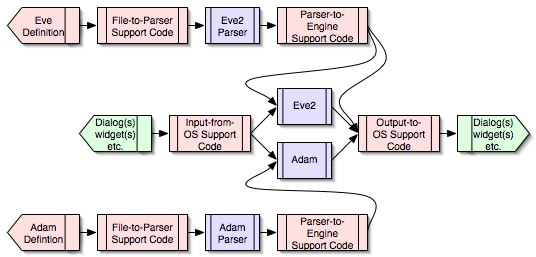
Figure 6: ASL Code Integration and Client Support Code
- There are clear boundaries between ASL code, client code, and the support code required to bind ASL to the client. Processes shaded in red represent code required of the client. Processes shaded in blue are provided by the ASL. OS routines are shaded in green.
- The process begins with Adam and Eve definitions describing an interface (a dialog, for example). The client supplies code to read in these definitions and relay them to the respective parsers for Adam and Eve. The parsers should interact with another suite of support code out the other side, which will relay pertinent information to Adam and Eve. Note too that the parser-to-engine support code might interact with widget set support code in initializing controls, windows, and the like. Adam and Eve will execute over the data provided to them, and communicate results to widget set support code. This code will convert data and parameters from the two engines into information useable by the OS. The application relating to the OS should be done at the client support code level. When the OS calls back to the client with events and data, the client support code should relay pertinent information back to Adam and Eve. Adam and Eve will update necessary parameters and send the notifications to the client support code, which relays important information back to the OS (a new wiget value, for example). This cycle of OS/Client/ASL/Client/OS will continue as the user interacts with the interface, and is the "event loop" model with Adam and Eve integrated.
- Most of the client integration code is fairly simple. The most complex piece of code is the widget support set as callbacks from Adam, Eve, their respective parsers, and the OS come together. Even then, the widget set support code is complex in terms of size, not algorithmic complexity. The code for a given routine is often just a matter of filtering and translating data, then routing that data to the appropriate destination. The most complicated processes in client code should lie outside this model. After all, this code is the means by which parameters are constructed for processes; the process itself should be independent of this code.
Appendix - Other Open Issues
- Currently Adam is loosely typed. It may be desirable to be able to declare a type for a cell and have the type enforced. If this is done, then a qualifier "optional" will be added to denote that the field could also contain "empty".
- Investigating XForms. Structured sheets and sheet inclusion.
Appendix - Grammars
- The grammars in this document are expressed using EBNF (Extended Backus-Naur Form) notation. EBNF is defined in the ISO-14977 standard. Available from the ANSI web site in PDF for a cost of $38.00. The final draft of the document is also available for free online.
- There are currently four grammars. They can be found in the following files:
- Property Model Language Reference
- Layout Library Language Reference
- Expression Reference (describes the lexical grammar and the expression grammar)
Appendix - Future Ideas
Visual Editor
- A visual editor for layout and property model libraries would be a great addition to ASL (the Begin example application is evolving in this direction). Eventually it will have a double editor view (outline and preview) but the preview window will also support direct manipulation. A source view (ala GoLive) may also be provided.
- Some support will be provided to simplify the process of cross platform previewing. The incorporation of the property model library will allow for active simulations.
- A tokenized string system can be successful in isolating what needs to be localized within an application. However, a major problem that still remains to be solved is determining the context of a string for the appropriate translation. It is a goal to be able to provide this context information in an editor in the form of a "find string..." command. This will be able to pull up the appropriate HI where the string appears. In the case of validation messages, the HI can be displayed in context with the property model rule that will trigger the message.
Features Under Consideration For Eve2
- An API for directly manipulating the Eve hierarchy could be useful for very dynamic views. Being able to bind a value to a node in a view allows for some simple direct setting of values - but not for structure manipulation. An XPath interface onto the Eve hierarchy could be a useful future addition.
- A maximum size constraint for a layout would be very useful for palettes. Currently you can set a minimal size that is of some use but requires hand inspection and adjustments for localization. A minimal solution would allow for an alternate view definition if a size constraint were violated. Another option would be to gracefully degrade the layout (breaking guide links, and formatting options) to force a dialog to fit. A combination of these two would most likely eliminate significant localization effort.
- A previous experimental version of Eve could adjust a layout for word wrapped text. This was fairly straightforward to implement and will most likely make it into a release of Eve2.
- The ability to directly specify menu items was not possible in Eve1 because the dataset was not rich enough and custom container layout was not allowed. In Eve2 there are several ways a client could support this feature.
- Adobe applications are currently moving to allow for custom key bindings at the application level. If this feature were to be extended into dialogs it may be desirable to have a feature in Eve or in a tokenized string system to support this. At this time however, there are no suggestions as to how such a feature would be implemented.